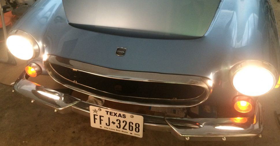
As you can tell from the nearly two-year absence of updates on this project, you can see that it’s no mere weekend project. Still, it’s not impossible, especially with the right tools and plenty of planning. After years of playing whack-a-mole with electrical gremlins in my 1971 Volvo 1800E, I decided to start from scratch with a brand-new wiring harness.
THE WIRING KIT
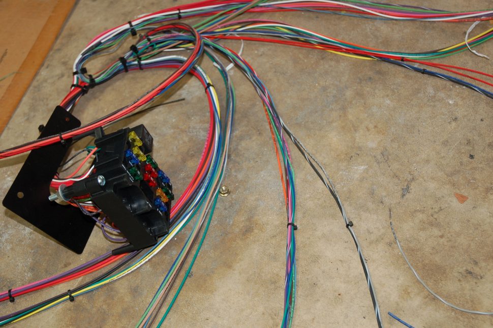
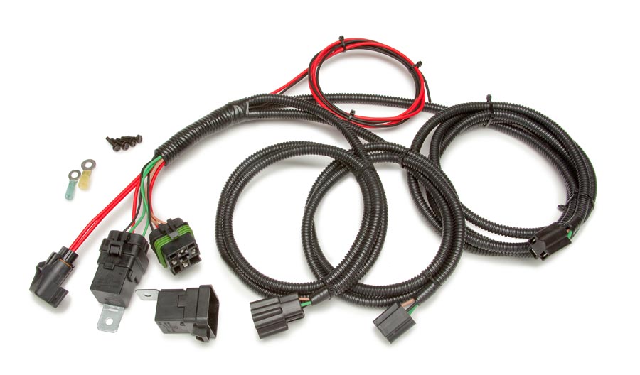
A universal wiring kit is just that, universal. The 12 circuit Painless fuseblock and harness (PN 764-10102) I decided to use is meant to be adaptable to most generic automotive electrical systems.
For instance: The horn circuit has its own fuse, horn relay, horn switch wire and horn activation wire. The headlight circuit assumes you will be using a standard foot dimmer switch and has wires for brights and low beams. Everything is very straightforward and clearly intended for wiring an American hotrod using some combination of domestic switch gear, alternator, turn signal indicators, etc.
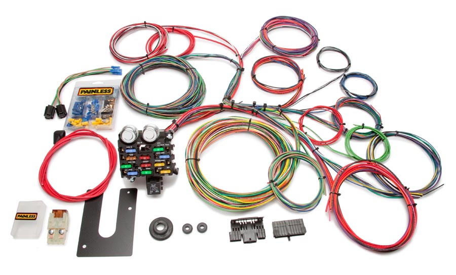
Full wiring kit. Photo courtesy of Painless Wires.
The fuse panel is well made and uses ATO blade-type fuses and standard automotive relays and flashers. All things you can find on the shelf of any U.S. auto parts store. The wires are all color-coded, pre-terminated to the fuse block, and labeled every 10 inches or so. I don’t have much experience with other aftermarket fuse block / harness products but I had very few issues with build quality or logical and physical layouts of the Painless system throughout this project.
Headlight relay upgrade, photo from Painless Wires
Along with the universal fuse block and wiring harness I also purchased a Painless headlight relay kit (PN 764-30815) as an upgrade to the lighting system. This harness uses relays to send power directly from the battery to the headlights, removing electrical load from the headlight switch and helping with voltage drop in the lighting system. I paired this with a new set of Hella H4 halogen headlights to replace my standard sealed beam bulbs. The lighting upgrade was a splurge but my night vision isn’t what it used to be and I’ve now been spoiled by modern headlights.
DOCUMENTATION AND PLANNING
If you were installing an aftermarket harness designed for a specific car, like a Chevelle or Mustang, I imagine the planning process is relatively simple and comes down mainly to thoughtful routing and termination (unplug the old, plug in the new). In the case of my car – adapting a universal harness to Volvo switch gear, gauges, charging scheme, etc. – this took some serious forethought and planning.
The documentation that came with the Painless system was adequate. I got the sense that the manual had been copied and pasted and amended many times since the 1990s. I read through the manual cover-to-cover several times and got a good sense of how to approach the install. I spread the harness out on the floor and started separating and laying out the wires to get familiar with them. The most valuable section of the manual is the grouping of tables describing each subsection of the harness (lights, ignition, tail section, etc.) wire by wire. My install manual was covered in notes by the end of the project and was a constant point of reference.
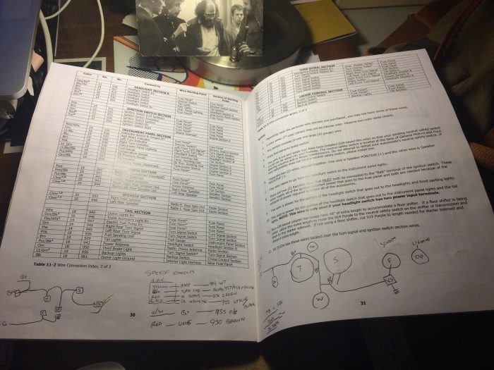
Painless performance install instructions
When shopping for a harness I’d advise downloading and comparing the various manuals first. You’ll learn more about the differences this way than by simply comparing product features.
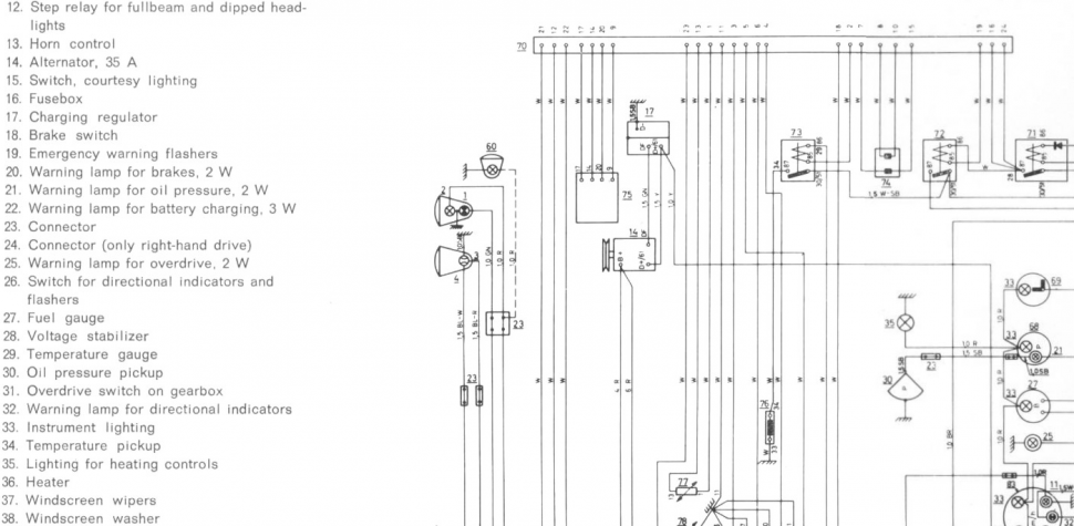
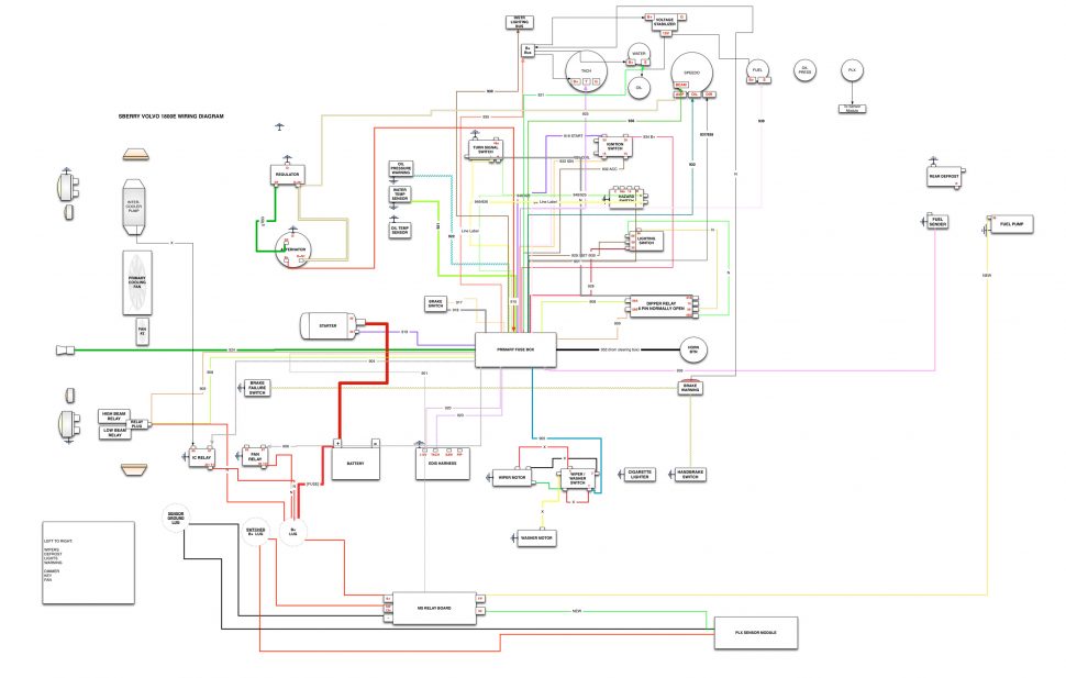
Excerpt from original Volvo Manual’s electrical diagram
My original Volvo service manuals include a foldout diagram of the stock electrical system. It’s complete and workable but it’s all in black and white and nearly very difficult to read quickly. A quick internet search turned up a handy alternative at colorwiringdiagrams.com. For $20 they shipped me a laminated 11-inch-by-20-inch diagram of the 1800E stock wiring drawn from scratch, color-coded and clearly labeled. I cannot exaggerate how useful this is for reference.
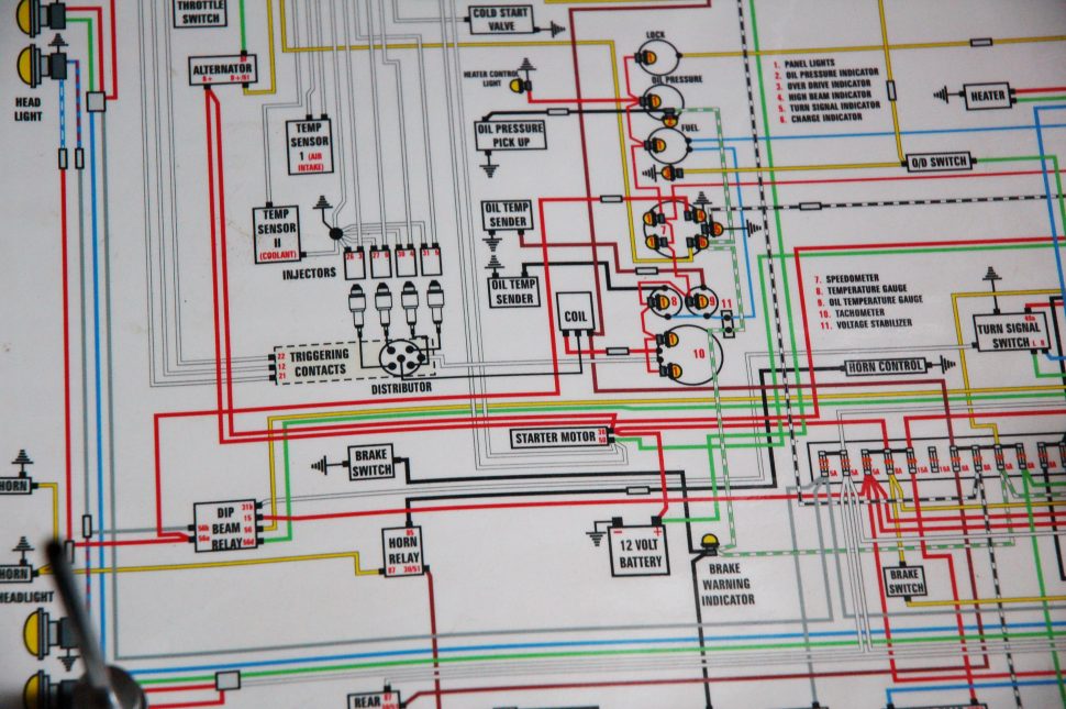
Excerpt from colored wiring dagram from Prospero’s Garage – colorwiringdiagrams.com
Since this wasn’t a straightforward install it was necessary to diagram the trickier sections before I ran or terminated any wire. I used a Macintosh diagramming program called Omnigraffle Pro (functionally similar to Visio for PC) to diagram how the Bosch, Lucas, and Painless pieces all hooked together. I inevitably got sucked in to diagramming the entire car which was probably unnecessary but satisfying. This bit of obsessive work can hang around as documentation for the lifespan of the car.
Lots of small logical problems cropped up at this stage. For example: The Painless harness expects separate left and right directional indicators. My Volvo speedo has a single indicator and hooking up both left and right wires would make both sides of the car flash when I engaged the turn signal. I found a simple circuit design on the internet and some diodes soldered inline solved the problem.
Below is an example of the wiring necessary to hook up the headlight switch to the dimmer, the hazards, the turn signals, and the new headlight relays.
This is an export from the Mac design program Visio. This is a working diagram that I created for this project that’s also handy keep around for reference.
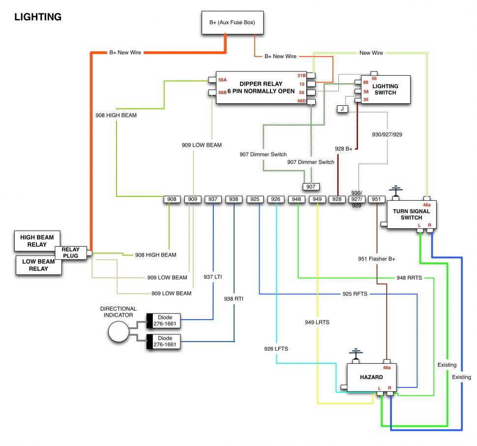
Diagram of the lighting system wiring, incorporating the new headlight relay kit.
TOOLS AND SUPPLIES
Any automotive electrical work will succeed or fail based on the quality of the connections and the thoughtful routing of wires. No more orange-handled $5 crimpers and bright blue wire caps. No more goopy electrical tape-wrapped wires sagging on to the exhaust manifold. No more intermittent shorts. Some small tool and supply investments can go a long way towards making your electrical work rugged and durable.
WIRE TERMINALS
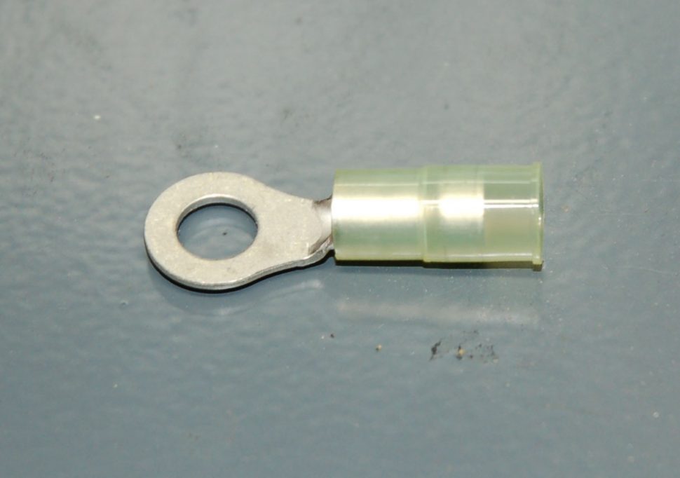
There are a lot of options for terminating connectors. The crummy “assorted” vinyl-covered connectors you can get for $5 just about anywhere should work okay when properly crimped, though the vinyl insulation doesn’t hold up well. Non-insulated connectors which you can easily revisit with solder and insulate with heat shrink tubing. Gold plated stuff for stereo nerds, Weatherpack and Molex connectors – it’s hard to decide which is best. In the end I wondered “What do the boat guys use?” and began looking around for marine-quality, double-crimp connectors. These are pretty straightforward: The first crimp actually collapses the terminal barrel on the copper strands of the wire, and the second, larger crimp, grabs the wire insulation sheath and provides strain relief. Ancor makes a whole range of marine grade terminals.
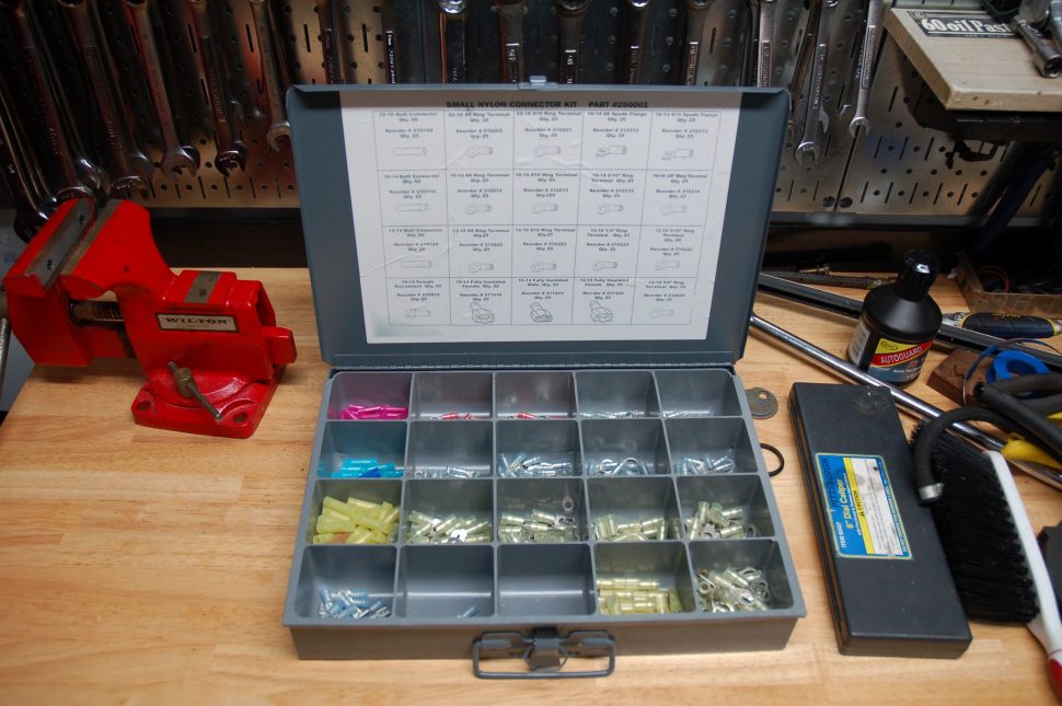
I bought a full organized kit of these connectors in a subdivided metal box. A bit pricey and I paid for a lot of butt connectors I probably won’t use, but the organization is welcome. Quality stuff and easily refillable by part numbers included in the case.
There are a couple of minor drawbacks to this style of connector. The bulk and length of the insulated connector, which provides much needed strain relief, can make it awkward to seal the connection with heat shrink tubing. It also adds to the length of the rigid end of the connection which can create some routing issues in tight places (under the dash).
I will not willingly join any debate about solder only vs. crimp and solder vs. crimp only. I mainly use crimp-only with heat shrink tubing where possible, and a dab of dielectric grease over the exposed opening of the terminal barrel. In some of the larger connections I lightly soldered the crimped connection as well but this simply wasn’t practical in terminating much of the wire on the car. I briefly played with a $4 bottle of liquid electrical tape and had not much luck with it.
I did not invest in Weatherpack connectors for this project but there are several areas where I resorted to multiple spade connectors where I wish I had made that investment.
RATCHETING DOUBLE CRIMPER
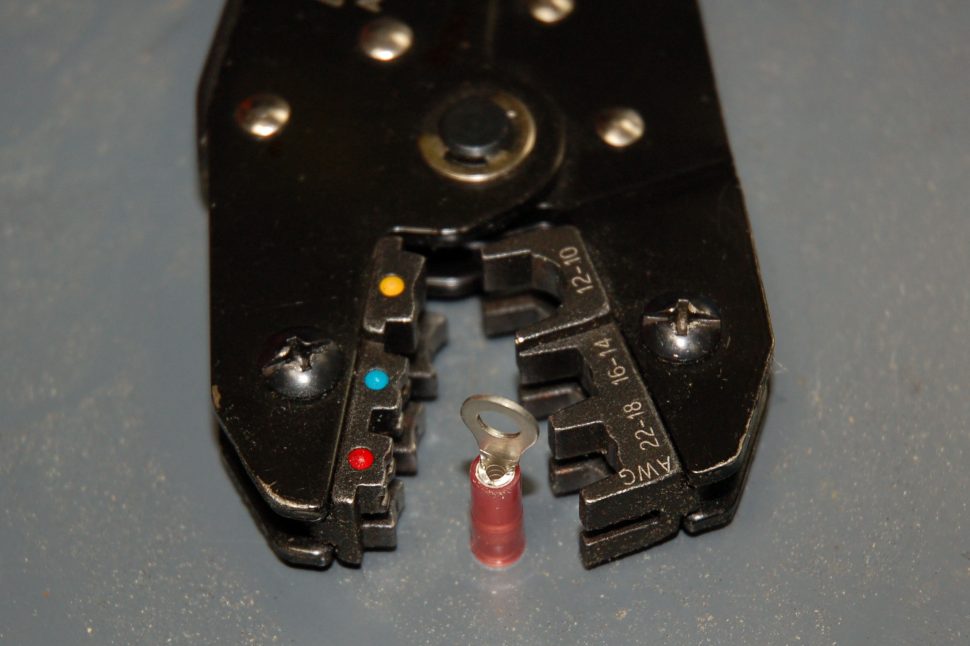
This one is made by Ancor and costs $75. There are nicer ones on the market but this certainly did the job for me. The crimper can be a little clunky in tight spaces but it gives very reassuring double crimps and the ratchet allows you to change hand positions in mid-crimp without slipping the crimper position. I occasionally found that the ratchet action would get hung up on very fat connectors and would require some convoluted work with a hammer to get it to release. I’ve never used a professional level of tool, but I have tried a couple in this price range and this one seems to be a solid value. It’s definitely light years beyond the orange-handled-mangler I’ve used in the past and I’d recommend making the leap to a mid-level ratchet style crimper if you haven’t already.
This tool can also be used on single crimp connectors – it’s pretty versatile.
SELF-ADJUSTING WIRE STRIPPERS
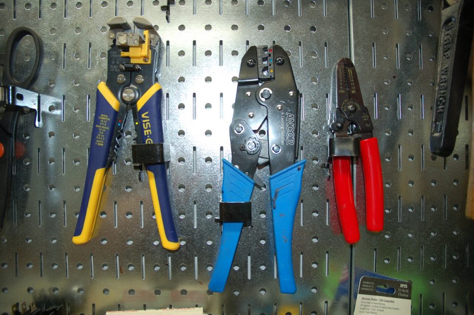
Irwin self-adjusting stripper on the left, traditional dedicated wire stripper on the right.
I worked with a couple of different types of wire strippers and found the self-adjusting type is helpful for quickly stripping wire on long projects. Nothing compares to ease of use and they work well in tight spaces. For years I had a Craftsman version of this type of stripper that worked incredibly well – I replaced that with an Irwin version that’s almost as good. Both were $25 from Sears. When they work they work well, but you’ll find plenty of instances where a well-made conventional stripper is needed. Spend a little money here on either or both styles.
POWERBRAID OR THE GENERIC EQUIVALENT
My Painless kit came with a small sample piece of Powerbraid wiring loom. It’s a flexible nylon mesh that’s easier to work with than rigid corrugated loom and it looks much nicer. Like the corrugated loom it’s split longitudinally and easy to slip over wiring runs. I used electrical tape in a few areas to clean up frayed edges and secure it in place. I ended up buying several sizes of the Powerbraid and finishing the harness in it. It doesn’t do terribly well with sharp turns but it’s otherwise terrific. I needed a few extra piece near the end of the project and tried a less-expensive generic alternative which also worked fine.
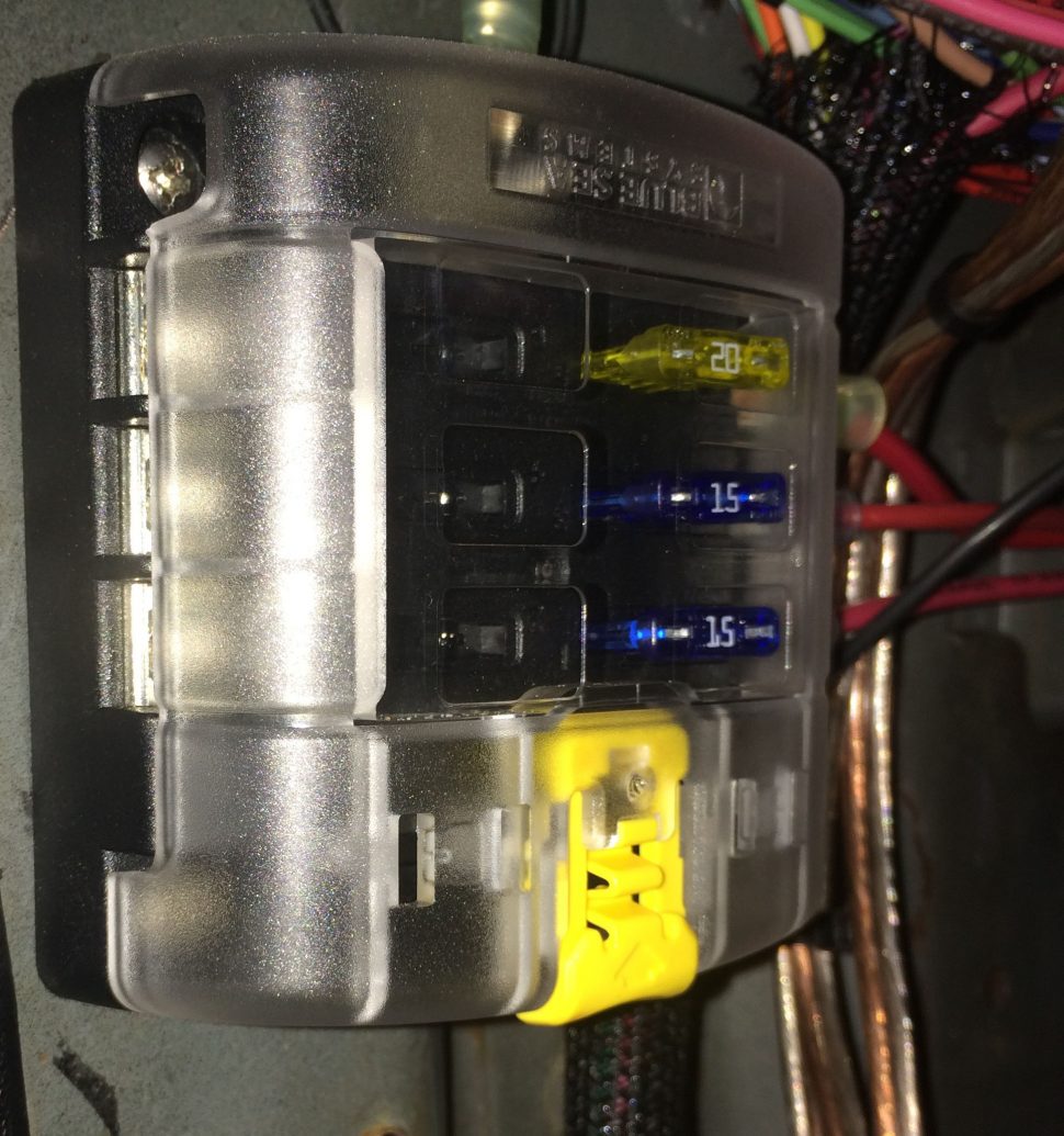
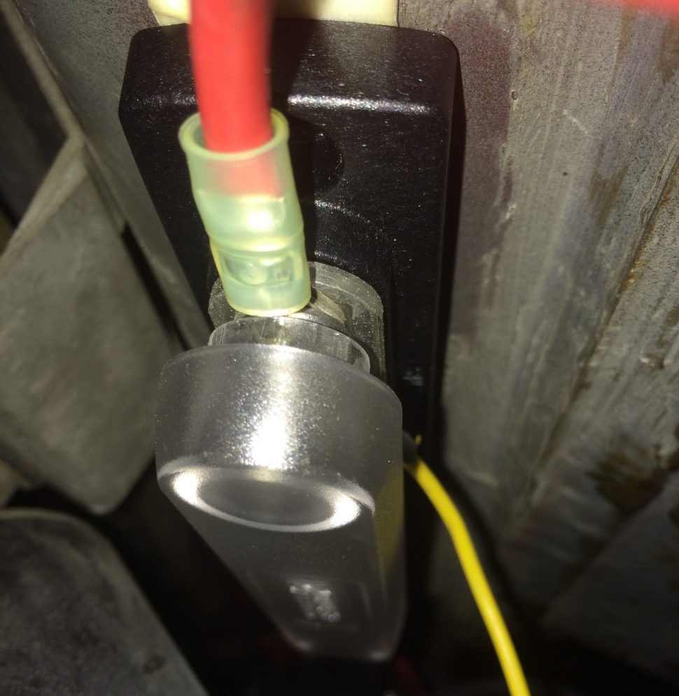
AUXILIARY FUSE PANEL
I added a small auxiliary fuse panel to handle 12V+ from the battery to fan relay, headlight relays, and dipper switch.
BLUE SEA DISTRIBUTION BLOCK
A bus bar is handy for cleaning up the common octopus of B+ connections you see growing off of the positive battery terminal in many hotrods. For my install I ran a single 10 gauge wire into the car, across a large 50 amp audio fuse, and then to this very nice distribution bus with a plastic cover. I grab 12V for stereo components and my engine management directly from this bus and it leaves a lot of room for expansion should I ever need it.
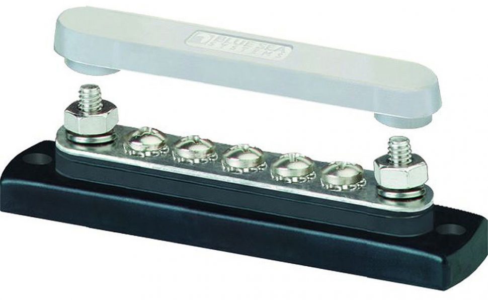
Bus Bar from Blue Sea
A bus bar is an elegant way to bring together many different connections
OTHER ODDS AND ENDS
- Small Zip Ties – Boatloads of them. The Painless instructions recommended to use them liberally – every few inches of harness run – and they supplied a nice cache of them with the harness kit. It’s very satisfying when you complete a run and confidently lock it down with zip ties.
- Scotch 3030 Electrical Tape. In some place you will need good old electrical tape and not all electrical tape is created equal. This is the most recommended brand and I found it to be easy to work with. It’s tidy with good adhesive strength without being too gooey or stretchy.
- Heat Shrink Tubing. Waytech wire has a variety of quality heat shrink tubing diameters you can buy in 25-foot spools. 3/8-inch diameter is the most versatile.
- Grommets: I managed to reuse some of the tired stock grommets from my original harness. I had difficulty finding anything quite as nice, most of what was available in parts stores or through internet searches seemed very chintzy – preserve whatever you can here or see if OEM replacements are available.
THE INSTALL
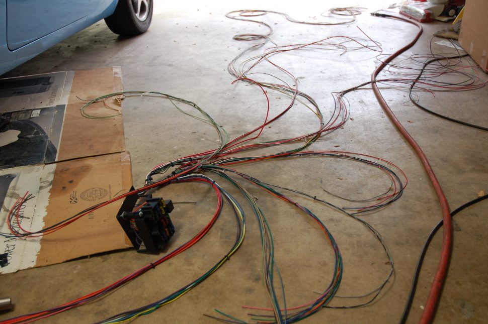
The install started with the removal of the original harness. First I removed the instruments and switches, took many photographs with my phone of everything I thought could be important. I cut the old harness in as few places as possible so I could have the original harness as reference and also so I could salvage portions if I needed to.
It’s educational to see how the Volvo engineers organized their harness, to see all the small routing, wrapping, and terminating details of their work. After spending so much time planning for this project it’s immediately obvious how much professional craft went into these details. My favorite part of working on any car is to see how the original designers solved complicated problems and then provide my own less-elegant solution in the name of progress.
I ended up reusing portions of the instrument harness, particularly the sections that connect the interior lights and the bundle of wires to the speedo. I also reused portions of the harness for interior lights and door jamb switches. Everything else came out and was replaced.
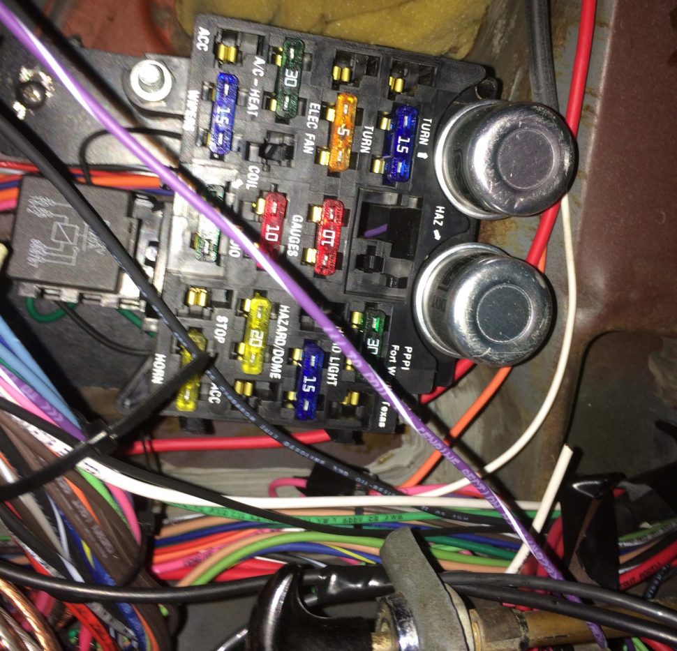
Painless Fuseblock installed upside down
The painless fuse block is surprisingly bulky compared to the stock Volvo (Lucas) fuse block and the Painless kits have all wiring runs pre-terminated at the block so you have to contend with these thick bundles of wires while mounting it. I ended up mounting the fuse block upside down under the dash. I used a small amount of rubber padding behind it for isolation and added cable support to the harness sections immediately after they exit the fuse block. Be aware that you will spend much of this job upside down, under the dash of your car. I’m a small guy, under 40, and I probably would have benefited from removing at least the driver’s side seat.
The fact that Painless labels every run of every wire in the kit is an indispensable feature. This job would otherwise be maddening. Deciding the physical routing of the wires takes trial and error. I found it useful to temporarily use wire trash bag ties and labeled pieces of masking tape to help keep things organized until I was ready to use zip ties.
Do not try this as a weekend project. Measure four times. Test two times. Cut once. Take your time. It’s important to nail down each section and test it before making final terminations. The lighting section and associated switches took the most time to rough in. This is a good place to leave yourself a lot of slack and use temporary wire nuts for junctions, alligator clips and test lights to verify a switch or circuit is going to work. Your best friends in this fight are a 12V dummy test light, and a digital multimeter for continuity tests. Spend the time to get it right. Walk away if you need to. If you’ve got it wrong you can figure it out and regroup.
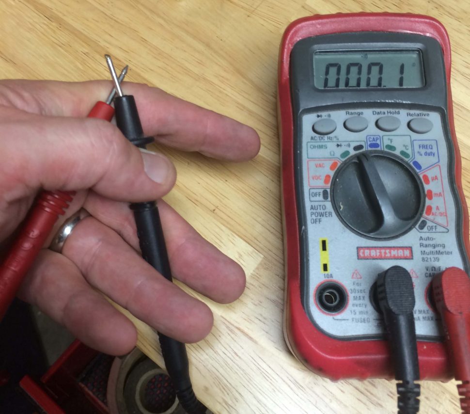
Digital Multimeter set up to test continuity. If you close the circuit between the leads the DVM beeps.
For fully testing circuits I used a battery charger with a 2 amp setting as suggested in the install manual. This sat in place of the battery and remained unplugged unless I needed to actively test something. Pull any fuses from the block of circuits not ready to see power. Note that the charger may not have enough current to activate certain relays. If a relay-based circuit doesn’t work as expected in testing you may need to test it with the actual battery.
PATIENCE
Tidiness is everything. Exposed wire bundles should get a zip tie every few inches. Reuse as much of the cable routing bits and mounting holes from the original harness as you can. Replace or (hopefully) reuse the stock firewall grommets. Mimic stock routing as closely as possible, particularly around most crowded areas behind the dash and also where the harness needs to transit to the back of the car.
No matter how good your planning is you will end up backtracking on some aspect of your work so always wait until the last possible moment to make things ‘final’. For various reasons leave yourself some reasonable amount of slack on every run.
Carefully laying out details of the harness is time-consuming but satisfying.
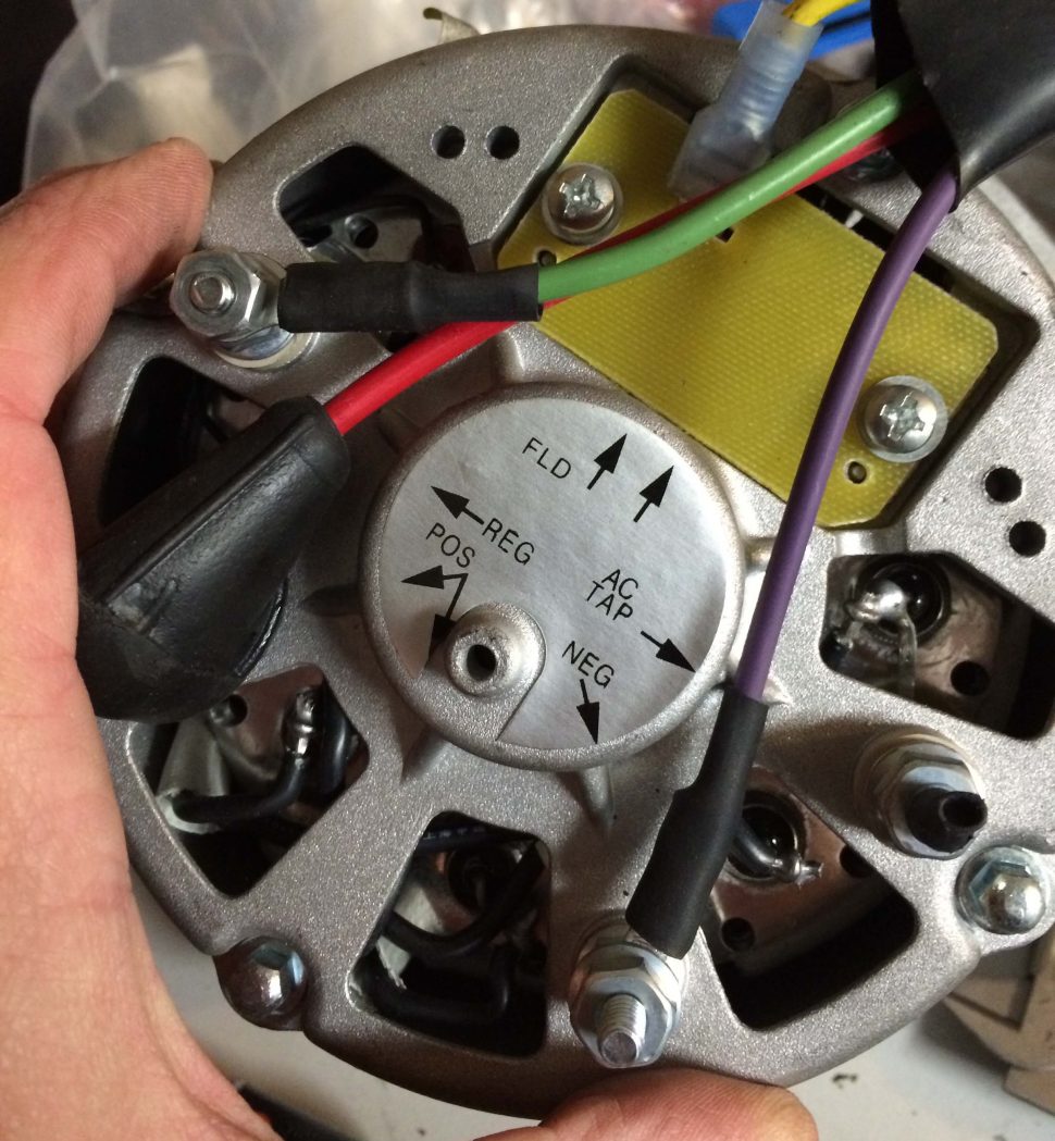
One of my only disappointments with the Painless kit was the length of the primary charging wire – it just wasn’t long enough to make a clean route to the alternator (without hanging over the engine). It’s a stout 10GA red wire and I would have liked to avoid splices and junctures in that path. I ended up making a harness for the back of the alternator and splicing the main charging cable with a stud and soldered ring terminals.
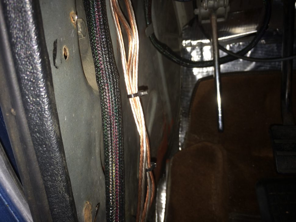
The tail section can be a bit of a mess. I used hangers with double sided tape (in the cable management section of the hardware store) to help secure the wire runs beneath the trunk lip. The important thing here is to avoid any situation where you can snag the harness while moving things (like floor jack and race tires) in and out of the trunk.
CONCLUSION
It works! I can ride down the road and stuff doesn’t flicker or catch on fire. I swear the car runs better. My headlights are bright. The car charges and every ground has been revisited. I spent more than 40 hours on this project. It was strangely enjoyable. We would love to hear any of your own tips for automotive wiring projects in the comments.
Tag
auto classifieds auto dealers bentley bmw bmw cars books for sale buick cadillac car classifieds car parts cars for sale cars wanted chevrolet classic cars for sale classic classifieds dodge ferrari ford ford cars hemmings jaguar jaguar cars lamborghini lincoln lotus maserati mercedes mercedes benz mercury cars muscle cars for sale oldsmobile packard parts wanted plymouth pontiac porsche porsche parts rolls royce services offered triumph used cars for sale volkswagen

Recent Comments